
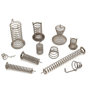
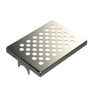
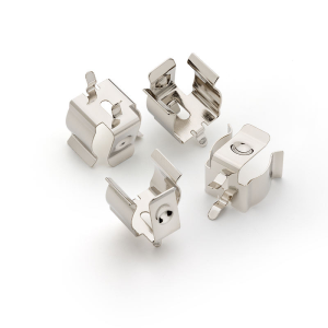
In high-volume metal component manufacturing, tooling represents one of the single largest upfront capital investments. Whether producing automotive structural brackets, intricate electronic connectors, or industrial enclosures, engineering teams face significant pressure to transition designs from CAD models into stable mass production. However, moving directly from part design to tool steel fabrication without a structured evaluation often introduces hidden structural flaws, material strain issues, and dimensional variations.
Unidentified design flaws that reach the tooling stage lead to costly engineering change orders (ECOs), extended trial loops, and delayed product launches. According to global manufacturing analysis from McKinsey & Company, up to 80% of product manufacturing costs and quality parameters are locked in during the initial design phase. Implementing a rigorous Design for Manufacturing (DFM) review early in the development lifecycle bridges the gap between theoretical part geometry and real-world metal forming physics, systematically mitigating tooling risks before steel is cut.
The True Cost of Unmitigated Tooling Risks
Tooling failures rare originate from poor tool steel selection alone. More often, they stem from component designs that violate basic sheet metal forming principles. When a part design does not account for material behavior under extreme tonnage, the progressive die or transfer tool absorbs the consequences.
Unaddressed design risks generally manifest in three distinct areas:
-
Excessive Engineering Change Orders (ECOs): Modifying hardened tool steel after initial tryouts can cost thousands of dollars per iteration and add weeks to project timelines.
-
Accelerated Tool Wear and Die Failure: Features that cause uneven stress distribution, such as sharp internal corners or tight radius bends, lead to premature punch chipping and die wear.
-
Unstable Mass Production: Parts manufactured with marginal forming windows exhibit high scrap rates, dimensional instability, and continuous press adjustments during production runs.
Key DFM Principles in Precision Metal Stamping
A comprehensive DFM analysis evaluates part geometry against material properties, press capabilities, and tooling mechanics. By adjusting features prior to tool production, engineers ensure predictable material flow and structural integrity.
Material Selection and Formability
Sheet metal alloys behave differently under tension and compression. Higher-strength materials offer weight savings but present lower ductility and higher springback. DFM reviews evaluate material utilization, grain orientation, and elongation limits to prevent tearing during deep drawing or tight bending operations.
Bend Radius and Grain Orientation
Bending metal parallel to its rolling grain increases the risk of micro-cracking along the outer bend radius. DFM guidelines dictate that bend radii should ideally equal or exceed the material thickness ($R \ge t$) and be oriented perpendicular or at a 45-degree angle to the material grain direction.
Edge Clearance and Hole-to-Bend Spacing
Placing pierced holes or cutouts too close to a bend line distorts the hole geometry during the bending phase. Standard engineering guidelines require a minimum distance of:
The minimum distance from hole edge to bend line shall satisfy:
\(d \ge 2t + R\)
where
d — Distance from hole edge to bend line,
t — Material thickness,
R — Internal bend radius.
Web Width and Feature Distance in Progressive Dies
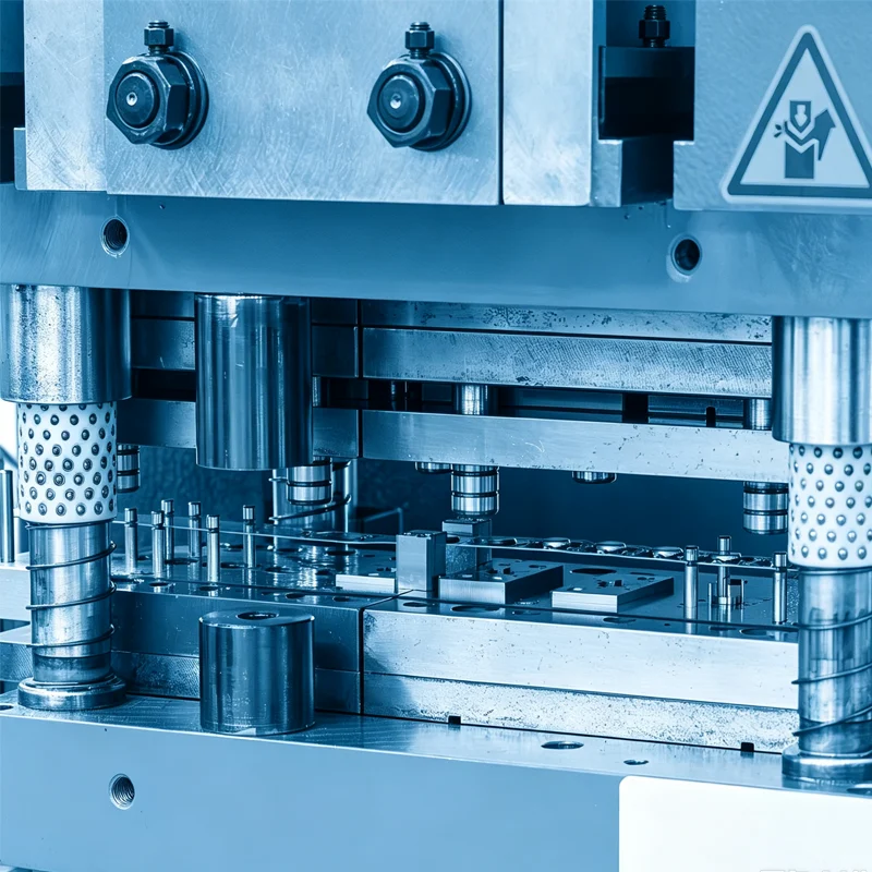
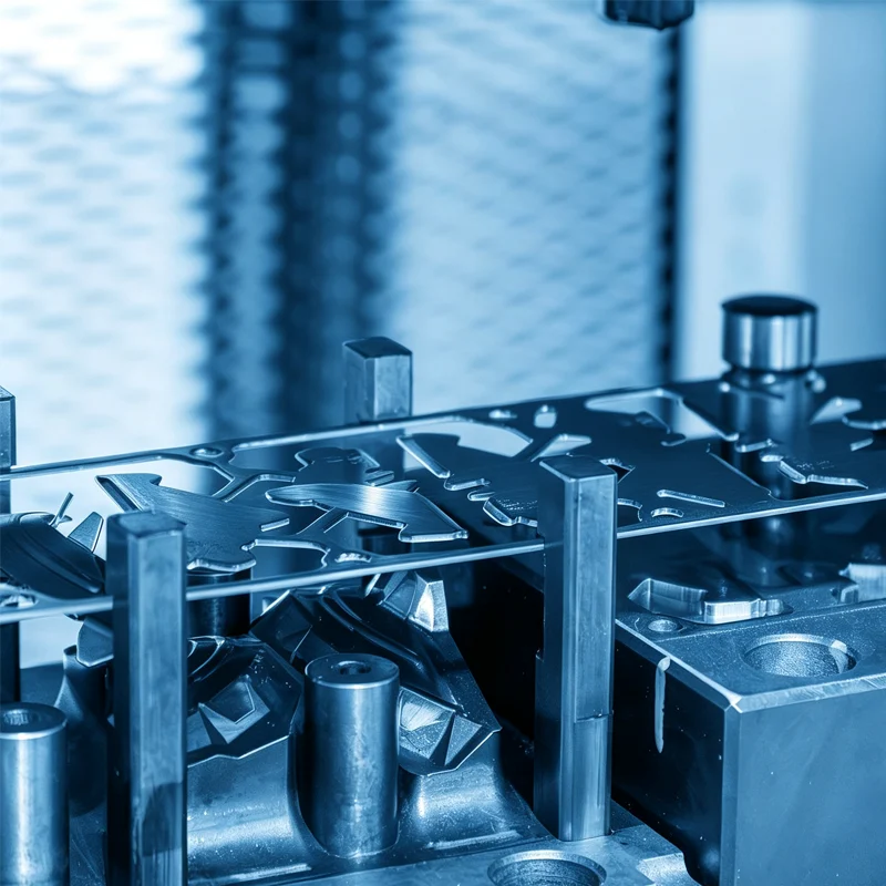
In progressive die stamping, parts remain attached to a carrier strip as they move through successive stations. Thin webs or narrow material sections between punched features can cause strip instability, feed misalignments, and premature die failure.
How DFM Optimizes Progressive Die and Tooling Performance
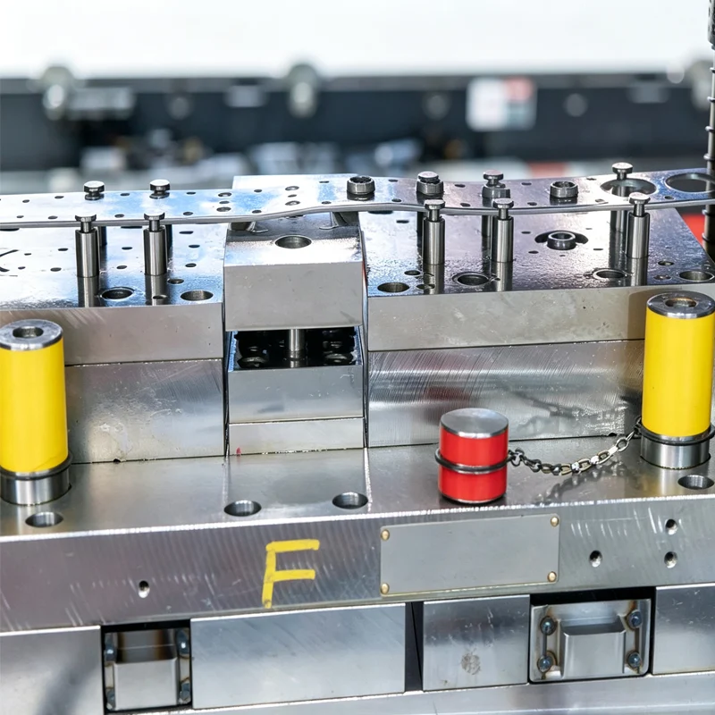
Applying DFM parameters directly impacts how progressive dies, transfer tools, and single-stage stamping operations perform on the factory floor.
Balancing Carrier Strip Layouts
A stable carrier strip ensures precise pitch control as the strip advances through multi-station dies. DFM analysis determines the optimal carrier layout—whether single, double, or center-carrier—preventing strip twist and jam-ups inside the press feeder.
Reducing Stamping Station Count
Complex geometries often require additional idle stations or forming steps to achieve final dimensions. By simplifying non-critical radii, combining forms, or optimizing blank shapes, DFM can reduce the overall station count, resulting in smaller die shoe footprints and lower initial tooling investment.
Managing Springback Prediction and Compensation
Springback occurs when metal attempts to return to its original shape after forming forces are released. Advanced simulation tools allow engineers to modify punch profiles and incorporate springback compensation directly into the CAD model before cutter paths are generated.
Mitigating Quality Risks Through DFM-Driven Tooling Design
Integrating DFM with quality planning ensures that component inspection criteria align with physical press room capability.Eliminating High-Stress Concentration Points
Sharp internal cutouts act as stress raisers during press strokes. Replacing sharp 90-degree internal corners with generous relief radii distributes forming loads evenly, reducing punch breakage and extending die life beyond standard maintenance schedules.
Standardizing Piercing and Blanking Clearance
Proper clearance between punch and die button determines shear surface quality and burr height. DFM specifies precise die clearances based on material tensile strength, minimizing burr generation and eliminating secondary deburring steps according to standards set by the Precision Metalforming Association (PMA).
Aligning Tolerance Stack-Ups with Manufacturing Reality
Over-toleranced part drawings significantly inflate tooling costs without adding functional value. DFM conducts tolerance stack-up analysis to align critical-to-quality (CTQ) dimensions with standard tooling tolerances, avoiding unrealistic precision requirements where commercial tolerances suffice.
Evaluating Engineering Capabilities in Metal Stamping Partners
Selecting an experienced manufacturing partner ensures that DFM principles are implemented effectively during early product development.To review your component drawings and manufacturing feasibility, consult our Engineering DFM Review services before finalizing tool designs.
When evaluating a stamping supplier’s engineering capability, procurement teams should confirm:
-
Early Involvements in DFM: The engineering team conducts formal manufacturability reviews prior to tooling quotation.
-
Simulation Capabilities: Utilization of finite element analysis (FEA) and auto-forming simulation software to predict metal flow and thinning.
-
In-House Tool Design and Maintenance: Complete control over tool geometry adjustments, die sharpening, and preventive maintenance programs.
-
Robust Quality Management: Compliance with international quality protocols, backed by certified measurement equipment such as CMM and optical sorters.
Manufacturing Perspective: OEM Case Example
During an early-stage review for an industrial equipment component, an OEM requested a deep-drawn steel bracket with sharp internal corners and tight hole-to-bend spacing. Initial simulation indicated a 35% material thinning rate along the corner radius—well above the 20% threshold for structural acceptance—and a high probability of side-wall cracking during high-speed stamping.Through a collaborative DFM review, the following adjustments were made before cutting tool steel:
-
Internal Radii Optimization: Corner radii were increased from 0.5 mm to 2.0 mm, reducing stress concentration and bringing material thinning down to a safe 14%.
-
Hole Offset Adjustment: Pierced hole locations were shifted 1.8 mm away from the primary bend axis, eliminating hole distortion and removing the need for a secondary drilling station.
-
Station Consolidation: The progressive layout was restructured, combining two forming stations into a single compound station.
Project Result: The DFM adjustments reduced initial tooling costs by 18%, cut die tryout lead time from 6 weeks to 3 weeks, and achieved a 0% defect rate across a 500,000-unit production run.
Strategic Advantages of Engineering-Led Metal Stamping
Partnering with an engineering-focused manufacturer translates complex technical specifications into reliable production outcomes. At Top Metal Stamping, our manufacturing framework is built around engineering rigor, robust tooling design, and strict quality control.
For custom projects requiring validated manufacturability and precision forming, explore our Custom Precision Stamping Parts to see how our engineering team supports complex OEM component requirements.
Integrated Engineering and DFM Analysis
Our dedicated engineering team evaluates component geometries, material choices, and forming mechanics before production begins. By conducting detailed DFM reviews, we identify risk areas early, reducing engineering change orders and accelerating time-to-market.
Advanced In-House Tooling and Die Development
We manage the entire tooling lifecycle—from initial CAD layout and simulation to high-precision machining and progressive die assembly. In-house tooling capabilities allow for tight control over die tolerances, rapid prototype turns, and efficient tool modifications.
High-Precision Multi-Stage Stamping
Equipped with modern press lines and automated feeding systems, our production facilities process a wide variety of metals—including stainless steel, aluminum, brass, and high-strength alloys—delivering consistent dimensional accuracy across low- and high-volume runs.
Comprehensive Quality Assurance
Operating under strict ISO quality management protocols, every production lot undergoes rigorous inspection. We utilize Coordinate Measuring Machines (CMM), optical measuring systems, and automated sorting technology to verify critical tolerances, surface finishes, and structural integrity according to standards outlined by the International Organization for Standardization (ISO).
What DFM Means for Your Product Strategy
Design for Manufacturing is not merely a pre-production checklist; it is a strategic approach to risk management in metal stamping. By evaluating component designs through the lens of material physics, press mechanics, and die construction, engineering teams eliminate costly downstream errors before capital is committed to tooling.
Investing in early DFM collaboration shortens development cycles, optimizes unit costs, and provides a stable foundation for long-term mass production success.
FAQs
1. How does DFM in metal stamping differ from DFM in plastic injection molding?
While both focus on manufacturability, metal stamping DFM deals with cold-forming physics, springback, grain direction, shear margins, and tonnage limits. Injection molding DFM focuses on fluid resin flow, gate locations, wall thickness uniformity, sink marks, and cooling rate contraction.
2. At what stage of product development should a DFM review take place?
A DFM review should take place during the concept refinement phase, before final CAD drawings are locked and long before tooling RFQs are issued. Conducting DFM early allows for structural adjustments without impacting project milestones.
3. Can DFM reduce unit part costs, or does it only affect tooling costs?
DFM reduces both. It lowers tooling costs by eliminating unnecessary die stations and complex features. It reduces unit part costs by maximizing material utilization (reducing scrap), increasing stamping press speeds, and minimizing defect rates during production.
4. What software tools are commonly used during metal stamping DFM analysis?
Engineers use 3D CAD platforms (such as SolidWorks, NX, or CATIA) alongside specialized metal forming simulation software (such as AutoForm or FASTFORM) to analyze strain distribution, predict springback, and optimize blank layouts.
5. How does material hardness affect the DFM process for stamped components?
Harder materials (such as full-hard stainless steel or high-strength low-alloy steel) exhibit greater springback, lower elongation limits, and require higher press tonnage. DFM adjusts bend radii, clearance ratios, and forming steps specifically to accommodate these material constraints.
About the Author
David Chen is a Senior Tooling & DFM Engineer at Top Metal Stamping with over 18 years of hands-on experience in precision metal forming, progressive die design, and OEM manufacturing.
He specializes in sheet metal formability analysis, DFM optimization, deep-drawn component engineering, and high-speed stamping process control. Working directly with global OEM procurement teams, industrial engineers, and Tier-1 automotive buyers, David focuses on bridging the gap between complex product designs and scalable, cost-effective manufacturing solutions.
References
-
McKinsey & Companyhttps://www.mckinsey.comInsights on Design for Manufacturability and value engineering in global manufacturing.
-
Precision Metalforming Association (PMA)https://www.pma.orgTechnical standards, die design guidelines, and stamping clearance specifications.
-
International Organization for Standardization (ISO)https://www.iso.orgInternational quality management standards and dimensional inspection protocols for manufactured metal components.
Request an Engineering Review
Ready to validate your metal component design and minimize tooling risk before production?
-
✔ Direct Access to Senior DFM Engineers
-
✔ Comprehensive Formability & Strain Analysis
-
✔ Optimized Progressive Die Layout Recommendations
-
✔ Transparent Material & Tooling Cost Evaluations
Contact Our Engineering Team to submit your CAD files for a complete Design for Manufacturing analysis.