
Why Stamping Programs Are Being Engineered for Volume Earlier
The market context behind volume-driven design
The global metal stamping market was valued at USD 226.3 billion in 2025 by IMARC Group, with Asia Pacific leading and the automotive sector named as a primary demand driver. Other research publishers report different totals because they define the scope differently, but they agree on the direction: stamped components are being specified at growing volumes across automotive, electrical and industrial applications.
What has changed for design engineers
A part that once shipped at a few thousand units per year may now be designed with a 100,000-unit annual forecast from day one. At that scale, a fraction of a second in cycle time, a few grams of scrap per strip pitch or one extra secondary operation is multiplied across the whole program. Design engineers are increasingly expected to think like process engineers before the first die is cut.
Why Design Decisions Made Before Tooling Determine Unit Cost
Tooling cost is fixed; every design choice is repeated
Once a stamping die is built, its cost is amortized across production. What remains variable is material consumption, press time, scrap, inspection effort and rework. Nearly all of these are set by the part geometry released to tooling, not by later production tuning.
The real price of a late design change
Changing a hole position or bend location after the die is machined typically means die modification, re-qualification of the part and, in some programs, customer re-approval. Changing the same feature on a CAD model costs an hour of engineering time. This asymmetry is why manufacturability review belongs before tool release.
Compliance exposure grows with volume
For automotive supply chains, quality expectations are formalized. AIAG describes IATF 16949:2016 as the standard defining quality management system requirements for automotive production, service and accessory parts, applied together with customer-specific requirements. Parts that are difficult to hold in tolerance across millions of cycles create audit and PPAP exposure long after the design is frozen.
Market Observation: Electrification Is Raising Repeatability Requirements
EV growth increases demand for stamped electrical parts
According to the IEA’s Global EV Outlook 2026, global electric car sales grew about 20% in 2025 to exceed 20 million units, reaching roughly 25% of new car sales. The IEA expects sales to rise further to around 23 million in 2026. Every one of those vehicles contains stamped terminals, busbars, connectors, shields and brackets.
Why electrical stampings are unforgiving
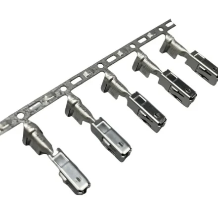
Electrical contact parts combine thin materials, tight dimensional windows and functional surfaces such as plating. Small variations in burr height, flatness or bend angle can affect contact resistance and assembly fit. High volume does not relax these requirements; it makes them harder to sustain.
Design-for-Stamping Principles That Hold Up at High Volume
The values below are commonly used starting points, not fixed limits. They vary with material, temper and thickness, so confirm them with your stamping supplier during design review.
Select material with formability and grain direction in mind
Material choice affects springback, cracking risk and die wear. Harder tempers and some copper alloys demand larger bend radii. Where a part has critical bends, orient the blank so bend lines run across, not along, the rolling direction.
Keep holes, slots and edges at safe distances
As a general guideline, hole diameters smaller than the material thickness raise punch breakage risk, and features placed closer to an edge than roughly 1.5 to 2 times thickness tend to distort. Holes located too near a bend can stretch into ovals during forming.
Specify bend radii and bend reliefs deliberately
An inside bend radius of at least one material thickness is a typical starting point for ductile materials. Adding relief notches where a bend meets a flat edge prevents tearing and bulging, and reduces the need for corrective operations.
Apply tight tolerances only where function requires them
Every additional tight tolerance adds inspection time and can force slower press speeds or extra stations. Separate functional dimensions from general ones on the drawing, and let non-critical features use standard stamping tolerances.
Define burr direction and edge condition
State which side of the part may carry the burr, and the maximum acceptable height. For contact surfaces, seal faces or assemblies with mating parts, this single note prevents disputes during first article inspection.
Understand when geometry moves into deep drawing
Cup-shaped, hollow or sleeve-type parts follow different rules than flat, bent parts. Draw depth-to-diameter ratio, corner radii and material ductility drive the number of draw stages. Early conversations with a deep draw stamping team can determine whether a part should be drawn, or redesigned as a formed and joined assembly.
Designing With the Die in Mind: Progressive Die Considerations
Strip layout drives material utilization
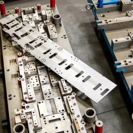
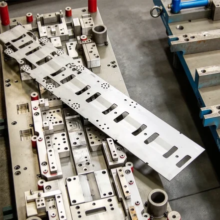
In high volume production, material is often the largest single cost element. Nesting the part orientation to reduce web scrap, and adjusting outline features to allow tighter pitch, can reduce material cost at no penalty to function. This analysis is central to progressive die stamping, where a strip of metal advances from station to station.
Carriers and pilots protect repeatability
The carrier strip holds the part through the die, and pilot holes register it at each station. Parts whose geometry leaves no room for a stable carrier or pilot locations force compromises that show up as dimensional drift over long runs.
Balance station count against die complexity
More stations can split difficult forming across steps, but they lengthen the die, increase maintenance points and raise tooling cost. The design objective is the simplest die that reliably holds the specification, and this is decided by geometry.
Plan secondary operations as part of the design
Plating, heat treatment, deburring, assembly and machining should be identified before tooling. Selective plating areas, masking needs and post-stamp machining allowances all affect part design. Reviewing secondary services alongside the drawing avoids re-engineering later.
Top Metal Stamping Perspective
How tooling and design review work together
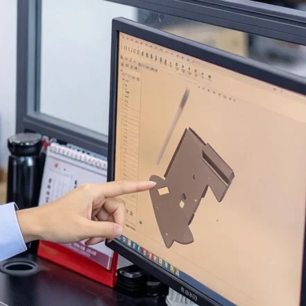
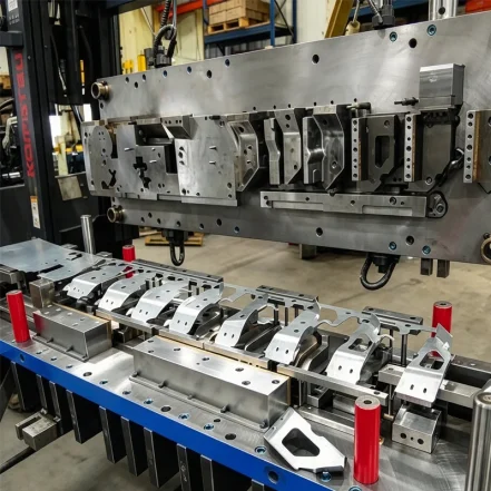
Top Metal Stamping designs, manufactures and maintains its own stamping tools, and its engineers use 3D CAD modeling to develop progressive dies in-house. In practice this means the team reviewing your drawing is the same team responsible for tooling and die design and die manufacturing. Feedback on hole spacing, bend relief or strip layout therefore comes from people who will build and maintain the tool.
Where these principles show up in our stamped products
The design principles above are applied across the company’s stamped product families. Buyers sourcing high volume electrical and mechanical components can review:
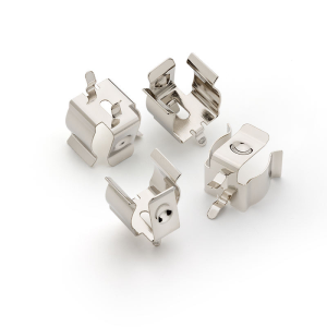
- Stamped terminals and connectors, including this battery terminal connector example, where contact geometry and plating consistency matter most
- Busbars, produced in materials such as copper alloys and aluminum, with options such as silver plating
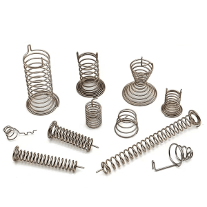
- Brackets and metal clips and fasteners, where spring properties and repeatable forming are critical
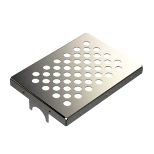
- Shields and deep-drawn components for electronics and automotive assemblies
Why this matters to procurement teams
From a sourcing standpoint, the value of a stamping partner is the risk it removes from the program:
- Tooling control: in-house die design, build and maintenance shortens the loop between a drawing change and a tool change, and reduces dependence on outside toolmakers.
- Certified quality system: the company holds ISO 9001:2015 and IATF 16949 certifications, which are typical prerequisites for automotive and EV supply chains.
- Early DFM feedback: the company’s instant quotation platform returns DFM feedback, pricing and lead times, so manufacturability issues surface at quotation rather than at tool build.
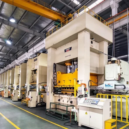
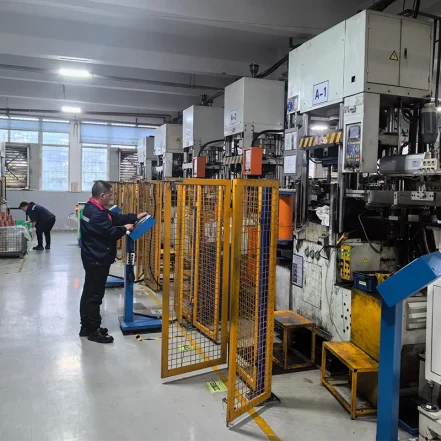
- Volume capacity: the company reports producing more than one million metal components each week across its facility.
- Application range: its products serve automotive, electric vehicle, electrical and appliance programs, which supports cross-industry material and process experience.
Practical Decision Framework for Engineers and Buyers
Before releasing the drawing
- ✓ Have hole, slot and bend features been checked against material thickness?
- ✓ Are tight tolerances limited to functional features?
- ✓ Are burr direction, grain direction and surface requirements stated?
- ✓ Has the annual volume forecast been shared with the stamping supplier?
Before approving the tool
- ✓ Has the supplier provided a strip layout with material utilization?
- ✓ Are carrier, pilot and station strategies explained?
- ✓ Is there a plan for die maintenance and spare components?
- ✓ Are secondary operations included in the quotation and timeline?
Before ramping to full volume
- ✓ Has the process capability been demonstrated on critical dimensions?
- ✓ Is the supplier’s quality system aligned with your industry requirements, such as IATF 16949 for automotive?
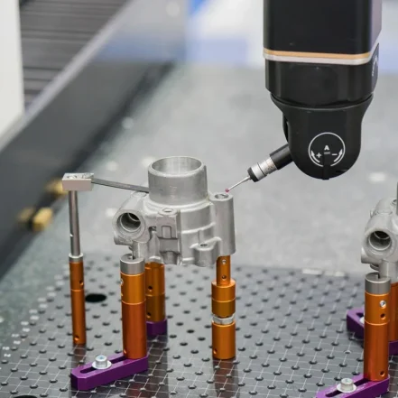
- ✓ Are in-process inspection points and gauging defined?
What This Means for Your Brand
From part design to supply chain resilience
Design for stamping connects directly to sourcing. A part that runs stably in one die, with minimal secondary operations and efficient material use, is easier to dual-source, easier to quote accurately and less exposed to cost swings.
The commercial implication
Products designed for manufacturability reach market faster, carry lower unit cost at scale and generate fewer quality escalations. For brands entering EV or electrical programs, where the IEA expects continued volume growth, this becomes a question of competitiveness.
Conclusion
Optimizing sheet metal parts for high volume stamping is mostly a matter of sequence. The decisions with the largest cost impact (material, feature spacing, bend geometry, tolerance strategy and strip layout) are made before the die exists. Engineers who involve their stamping partner at the design stage, and buyers who verify tooling control and quality certification, protect both unit cost and delivery over the life of the program.
FAQ
1. At what volume does progressive die stamping become more economical than other processes?
There is no universal threshold. The break-even depends on part geometry, material and tool complexity. As a rule, once annual demand reaches tens of thousands of pieces and the part suits strip-fed forming, the tooling investment is usually recovered through lower per-part labor and cycle time. A supplier can model the crossover using your drawing and forecast.
2. Should I involve the stamping supplier before the design is finished?
Yes. Feedback on strip layout and forming feasibility is most valuable while changes are still just CAD edits. Sharing a preliminary model and the target volume is usually enough for a first review.
3. Which drawing details most often delay stamping tool approval?
Missing burr direction, unclear datum structure, over-specified tolerances on non-functional features, and undefined plating or surface requirements are common causes of back-and-forth.
4. How does material thickness variation affect high volume production?
Coil thickness tolerance influences bend angle, springback and press load. Specifying the coil tolerance grade, and confirming incoming material inspection, helps keep the process centered over long runs.
5. What certifications should I request from a stamping supplier for automotive or EV parts?
ISO 9001 is the general baseline, while IATF 16949 is the automotive-specific quality management standard, applied together with customer-specific requirements. Confirm that the certificate scope covers the stamping site that will actually produce your part.
About the Author
Jack is a Senior Stamping Engineer at Top Metal Stamping with more than 20 years of experience in precision metal stamping, progressive die design and high volume production. He specializes in design-for-manufacturing (DFM) review, tooling optimization, strip layout analysis and the development of stamped components for automotive, EV, electrical and industrial applications.
Throughout his career, Jack has worked with global brands, manufacturers and sourcing teams to improve stamping part manufacturability, reduce tooling risks and achieve stable mass production through engineering-driven solutions. His focus is on connecting product design, tooling development and production control to deliver reliable, cost-effective stamped components.
At Top Metal Stamping, Jack supports customers from early design evaluation and tooling review through production validation, helping engineering and procurement teams make informed decisions for long-term supply success.
References
- IMARC Group, Metal Stamping Market
https://www.imarcgroup.com/metal-stamping-market - International Energy Agency (IEA), Global EV Outlook 2026
https://www.iea.org/reports/global-ev-outlook-2026/trends-in-electric-cars - Automotive Industry Action Group (AIAG), IATF 16949:2016
https://www.aiag.org/expertise-areas/quality/iatf-16949-2016
Why Global Manufacturers Choose Top Metal Stamping
✔ 20+ Years of Precision Metal Stamping Experience
✔ In-House Die Design, Manufacturing and Maintenance
✔ ISO 9001:2015 and IATF 16949 Certified Quality Systems
✔ DFM Feedback Through Instant Quotation
✔ Materials and Processes Covering Terminals, Busbars, Brackets, Shields and Deep-Drawn Parts
✔ Support from Prototyping to Volume Production
Whether you are planning a new terminal, busbar, bracket or deep-drawn component, our engineers can review your drawing for manufacturability before tooling begins. Send your CAD files for a DFM review to discuss your next stamping project.