
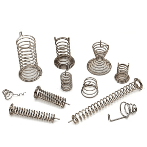
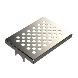
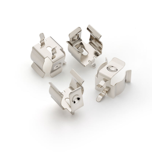
Why Part Design Has Become a Production-Cost Decision
For OEM buyers sourcing precision metal components, a drawing that meets functional requirements is only the starting point. The design must also support repeatable forming, stable dimensions, manageable tooling wear, and consistent quality throughout the production run.
The Automotive Steel Partnership’s High-Strength Steel Stamping Design Manual (2024) provides practical guidance for material engineers, product designers, and die process planners working with high-strength steel. The underlying sourcing consideration is straightforward: material behavior, part geometry, and tooling strategy need to be evaluated together before a production die is finalized.
For procurement teams, resolving design risks early can reduce the likelihood of tooling revisions, production interruptions, excessive scrap, and disputes over dimensional acceptance. These risks become particularly important when a component is expected to run at high volumes over an extended production lifecycle.
For buyers evaluating a custom metal stamping supplier, design readiness should therefore be part of supplier qualification—not a task left entirely to the tooling stage.
1. Part Geometry Determines More Than Tooling Complexity
Hole and Slot Placement
Holes, slots, and narrow cutouts affect punch strength, material deformation, and the available space between adjacent features. When these features are placed too close to an edge or bend, the material may distort, while the tooling may become more vulnerable to premature wear or breakage.
Designers should evaluate feature dimensions against material thickness, strength, ductility, and the selected stamping process. Generic design ratios are useful for preliminary screening, but they should not replace a process-specific engineering review.
Bend Radius and Material Strain
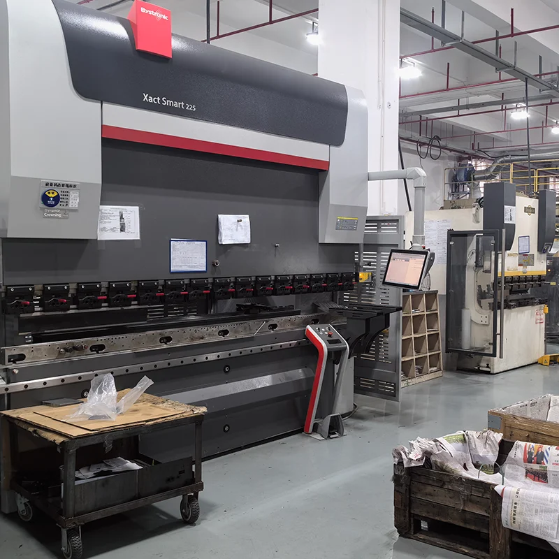
A bend that appears simple on a CAD drawing can become a production risk when the material cannot accommodate the required strain.
The appropriate inside bend radius depends on alloy, temper, thickness, grain orientation, and forming conditions. An unnecessarily tight radius may increase cracking risk, while a poorly coordinated bend geometry can complicate tooling and dimensional control.
For high-volume programs, buyers should confirm that critical bends have been reviewed against the proposed material specification and forming sequence.
Feature Position Relative to Formed Areas
Holes or slots near bend lines may shift, stretch, or become distorted during forming. If these features control assembly alignment, electrical contact, or fastening, even a small dimensional change can affect downstream operations.
Where practical, designers should consider moving sensitive features away from heavily deformed regions. If the geometry cannot change, the supplier should identify the necessary tooling strategy and inspection method before approval.
2. Material Specifications Must Match the Forming Strategy
Alloy, Temper, and Thickness
A material designation alone does not fully describe how a sheet or coil will behave during stamping. Mechanical properties, thickness variation, surface condition, and material temper can influence forming loads, springback, and dimensional consistency.
For buyers, the material specification should define the required grade, temper or condition where applicable, thickness and tolerance, and relevant mechanical requirements. Substitutions should be reviewed for their effects on forming performance and finished-part acceptance.
Grain Direction and Springback
Rolled sheet materials can exhibit directional differences in forming behavior. Grain orientation may influence bend cracking, particularly in applications involving demanding radii or less ductile materials.
Springback also affects the final angle and geometry after forming loads are released. Its magnitude depends on material properties, geometry, thickness, and tooling conditions.
The practical implication is that critical angles and formed dimensions should be evaluated during tooling development rather than assumed to match the CAD model automatically.
When Material Changes Require Revalidation
A change in material supplier, temper, coating, or thickness can affect an established stamping process. Even when a replacement material appears equivalent on paper, its actual forming response may differ.
OEM purchasing teams should establish a documented material-change approval process. This is particularly important for components used in electrical connections, automotive assemblies, and other applications where fit or performance depends on tightly controlled characteristics.
3. Progressive Die Design Requires Early Engineering Alignment
Strip Layout and Material Utilization
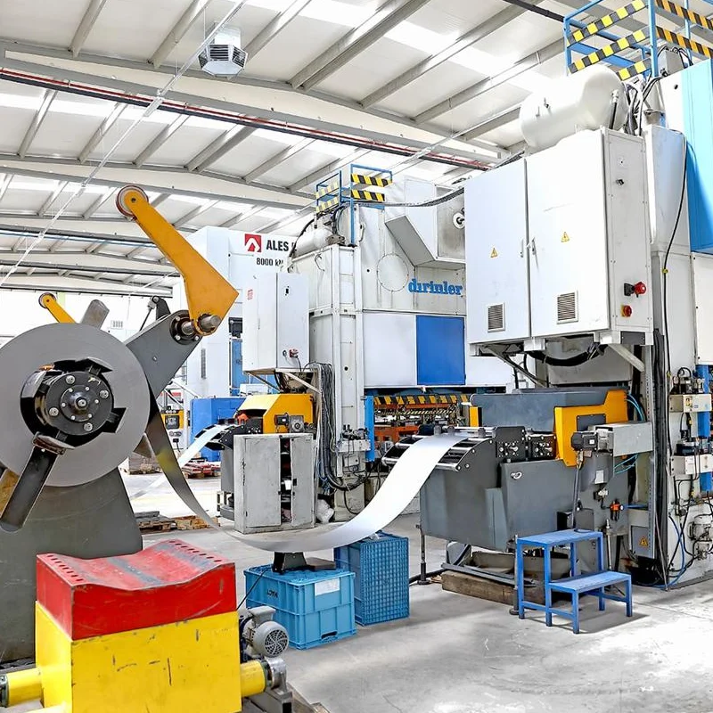
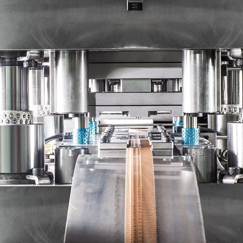
In progressive die stamping, the strip advances through multiple stations that perform operations such as piercing, bending, forming, and cutoff.
The strip layout influences material utilization, carrier stability, station spacing, and the sequence in which features are created. A layout optimized only for low material consumption may create challenges for part support or dimensional consistency.
Before tooling approval, buyers should understand the proposed process route and whether the supplier has evaluated both material utilization and production stability.
Station Sequence and Part Stability
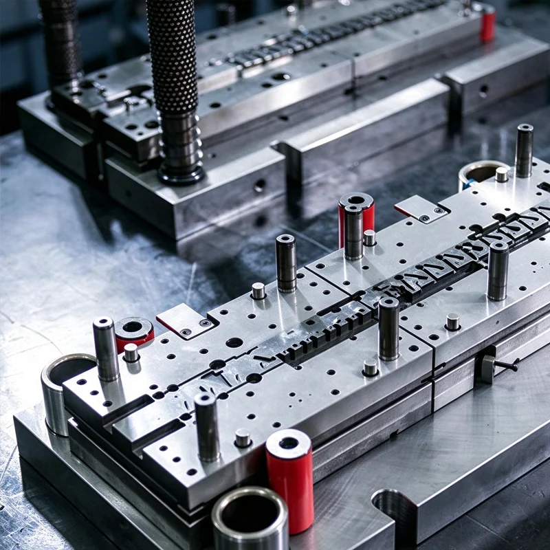
The order of operations determines how the part is supported and deformed throughout the die. Features formed too early may be affected by later operations, while insufficient support can contribute to positional variation.
The appropriate sequence depends on part geometry, material properties, press capability, and tooling design. Complex components may require additional forming or restriking operations to achieve the intended geometry.
Top Metal Stamping’s progressive die stamping capability covers strip materials from 0.05 mm to 2.5 mm thick and up to 150 mm wide, according to its published service information. These are stated capability parameters, not a guarantee that every geometry or tolerance is feasible; individual parts require engineering review.
Tooling Design and Production Repeatability
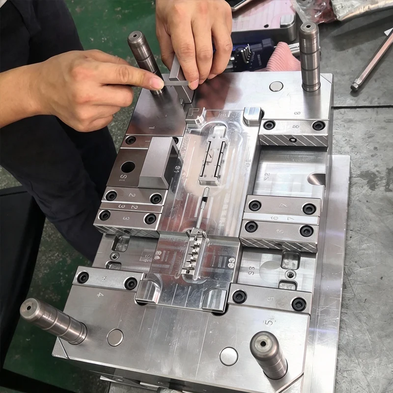
A production die must maintain alignment and controlled interaction between punches, die sections, guides, and other working components. Tool wear and changes in operating conditions can affect the dimensions of parts produced over time.
For procurement teams, the important question is how tooling design, maintenance, and inspection will support repeatable production over the expected program life.
Top Metal Stamping provides tooling and die design and development services, allowing customers to discuss part geometry, tooling feasibility, and manufacturing requirements before committing to a production approach.
4. Tolerances Should Reflect Functional Requirements
Separate Critical Dimensions From Noncritical Dimensions
Applying tight tolerances to every feature can increase manufacturing and inspection demands without necessarily improving product performance.
Instead, drawings should identify dimensions that affect assembly, electrical contact, sealing, alignment, or other functional requirements. Less critical features can be specified according to realistic process capability and application needs.
This approach gives the supplier a clearer basis for process planning and helps procurement teams compare quotations on equivalent technical requirements.
Account for Tolerance Stack-Up
When stamped components are assembled with other parts, individual dimensional variations can accumulate. A component that passes its own inspection may still contribute to an assembly fit problem.
Engineers should evaluate the relationship between locating features, mating surfaces, hole positions, and formed angles. Where necessary, the design should establish functional datums and an appropriate measurement strategy.
The ISO 2768 dimensional-tolerancing reference provides background on general tolerances for linear and angular dimensions. Buyers should confirm which standards and drawing requirements apply to their project rather than assuming a general tolerance standard covers every feature.
Define Inspection and Acceptance Before Production
The drawing, inspection plan, and purchase specification should communicate the same acceptance requirements. If a dimension is critical, the parties should agree on how it will be measured, where it will be measured, and what constitutes an acceptable result.
For complex parts, this may include first-article inspection, in-process dimensional checks, and periodic verification during production. The specific plan should reflect part risk, volume, and customer requirements.
5. Match the Component Design to the Right Manufacturing Process
Progressive Stamping for Repeated Complex Features
Progressive die stamping may be appropriate for components that combine multiple cutting and forming operations and require sustained production volumes.
Potential applications include electrical contacts, terminals, clips, lead frames, and other precision components. Its suitability depends on geometry, material, annual demand, tooling investment, and the required production lifecycle.
For buyers sourcing these parts, Top Metal Stamping’s custom metal stamping products include terminals, shields, and other custom stamped components. The value of evaluating these product categories is that the discussion can start from the component’s functional requirements and production needs, rather than from tooling price alone.
Deep Drawing for Hollow or Cup-Shaped Components
Deep drawing is a different forming approach used to create hollow or deeper geometries from sheet metal. It may be more appropriate than a conventional progressive stamping route when the component’s depth and shape require controlled material flow.
Top Metal Stamping’s deep draw stamping service supports discussion of custom drawn parts, material selection, tooling, and secondary operations. The appropriate process should be determined from the part geometry, material behavior, dimensional requirements, and expected volume.
Secondary Operations and Assembly
Some parts require deburring, finishing, machining, or assembly after stamping. These operations can affect total landed cost, lead time, and the dimensional characteristics of the finished component.
Buyers should specify the required final condition—not just the shape coming out of the press. For example, an edge condition that is acceptable before assembly may not be suitable for a component that contacts another part or must meet a specific surface requirement.
6. What OEM Buyers Should Confirm Before Tooling Approval
Engineering Data and Drawing Readiness
Before requesting a final tooling quotation, prepare the latest controlled drawing and available 3D model. Include the material specification, critical dimensions, tolerances, surface requirements, expected annual volume, and anticipated program life.
Where the design remains flexible, identify which features are negotiable and which are essential to product function. This gives the supplier a practical basis for proposing design adjustments.
DFM Review and Risk Resolution
A design-for-manufacturability review should identify risks involving material flow, feature placement, forming sequence, tooling access, and dimensional control.
Each significant issue should have a clear disposition: retain the design with an agreed control method, revise the geometry, or evaluate an alternative process. Open issues should be resolved before they become expensive tooling changes.
Production Validation and Change Control
Before mass production, agree on the sample approval process, inspection documentation, material traceability requirements, and criteria for accepting the first production run.
The project should also define how drawing revisions and material substitutions are approved. A controlled change process helps prevent different versions of the same component from entering production or the supply chain.
Practical Decision Framework for Procurement Teams
Before releasing a metal stamping project for tooling, confirm the following:
- The material grade, temper, and thickness are clearly defined.
- Critical holes, slots, bends, and formed features have been reviewed for manufacturability.
- The proposed stamping process is suitable for the geometry and production volume.
- Functional dimensions and inspection methods are documented.
- Secondary operations and finished-part requirements are included in the quotation scope.
- The supplier has identified major design and tooling risks.
- Sample approval, change control, and production acceptance requirements are agreed upon.
These checks help buyers evaluate suppliers on engineering alignment and production readiness—not merely the initial tooling quotation.
What This Means for Your Sourcing Strategy
A stamped component’s long-term cost is shaped by more than its material content or the price of the die. Design stability, production repeatability, maintenance requirements, and inspection demands all influence the commercial performance of a sourcing program.
For OEM buyers, early collaboration between product engineering, purchasing, quality, and the stamping supplier creates a clearer path from design approval to volume production. It also makes supplier quotations easier to compare because the technical assumptions are defined before tooling begins.
The objective is not to make every part more complicated or to apply the tightest possible tolerance. It is to establish a design and manufacturing strategy that consistently meets functional requirements throughout the intended production lifecycle.
Conclusion
Reliable high-volume metal stamping begins with alignment between part geometry, material behavior, tooling design, and quality requirements.
OEM buyers can reduce avoidable production risks by resolving critical features early, selecting a suitable forming process, defining realistic tolerances, and agreeing on validation requirements before tooling approval. These decisions provide a stronger basis for evaluating manufacturing partners and managing long-term component supply.
FAQ
1. What information should an OEM buyer provide for a metal stamping tooling quotation?
Provide a controlled engineering drawing, available 3D CAD files, material and thickness specifications, annual volume, critical tolerances, finishing requirements, and the expected program lifecycle. Identify any unresolved design requirements so the supplier can assess feasibility before finalizing the tooling proposal.
2. Can a stamped part be redesigned after the production die is completed?
Yes, but the impact depends on the proposed change and the existing die architecture. Some revisions may require minor tool adjustments, while changes to feature positions, material thickness, or forming geometry may require substantial modifications and renewed validation.
3. Is progressive die stamping always the most economical choice for high-volume parts?
No. Production volume is important, but geometry, tooling investment, material utilization, secondary operations, and expected program life also affect total cost. The most economical process should be evaluated over the intended production lifecycle rather than by piece price alone.
4. Why can a stamped part fail assembly inspection even when its dimensions meet the drawing?
The issue may involve tolerance stack-up, datum selection, measurement methods, or interactions between multiple components. Functional assembly requirements should be considered when establishing the drawing and inspection plan.
5. When should a material substitution trigger a new production review?
A review is appropriate when a change could affect formability, springback, strength, thickness, surface condition, corrosion performance, or other specified characteristics. The required validation should be determined by the component’s function and the customer’s change-control requirements.
6. What should buyers review before approving production samples?
Confirm that the samples were produced using the intended material and representative production tooling and process conditions. Review dimensional results, material documentation, appearance, finishing, and any application-specific acceptance criteria before authorizing mass production.
About the Author
David is a tooling and die engineering specialist at Top Metal Stamping with more than 20 years of experience in mold and die engineering. He focuses on tooling development, precision metal stamping, manufacturability reviews, and production consistency for OEM components. His expertise includes evaluating part geometry, material specifications, dimensional tolerances, and die design considerations before tooling approval. David helps OEM buyers and engineering teams identify potential manufacturing risks early, align tooling decisions with production requirements, and support reliable quality in high-volume stamping projects. His practical perspective connects product design, tooling performance, and long-term manufacturing efficiency.
References
- Auto/Steel Partnership — High-Strength Steel Stamping Design Manual (2024)
https://a-sp.org/downloads/high_strength_steel_stamping_design_manual-2/ - Xometry — Metal Stamping Design Standards and Considerations (updated March 12, 2026)
https://www.xometry.com/resources/industry-design-tips/stamping-design-tips/ - International Organization for Standardization (ISO) — ISO 2768-1: General Tolerances
https://www.iso.org/standard/7748.html
Planning Your Next Stamping Program?
Top Metal Stamping supports custom metal component projects through tooling and die development, progressive die stamping, deep draw stamping, and related manufacturing services.
If you are evaluating a new component or preparing a design for high-volume production, share your engineering drawings and applicable requirements for a technical review.